
With only a floor load and attic above to support, I felt that this 4-foot clear span wouldn’t be a problem.
INSTALL SUPPORT BEAM IN CEILING INSTALL
Tip: install mid-height horizontal or diagonal bracing on the temporary wall to prevent the studs from bowing.

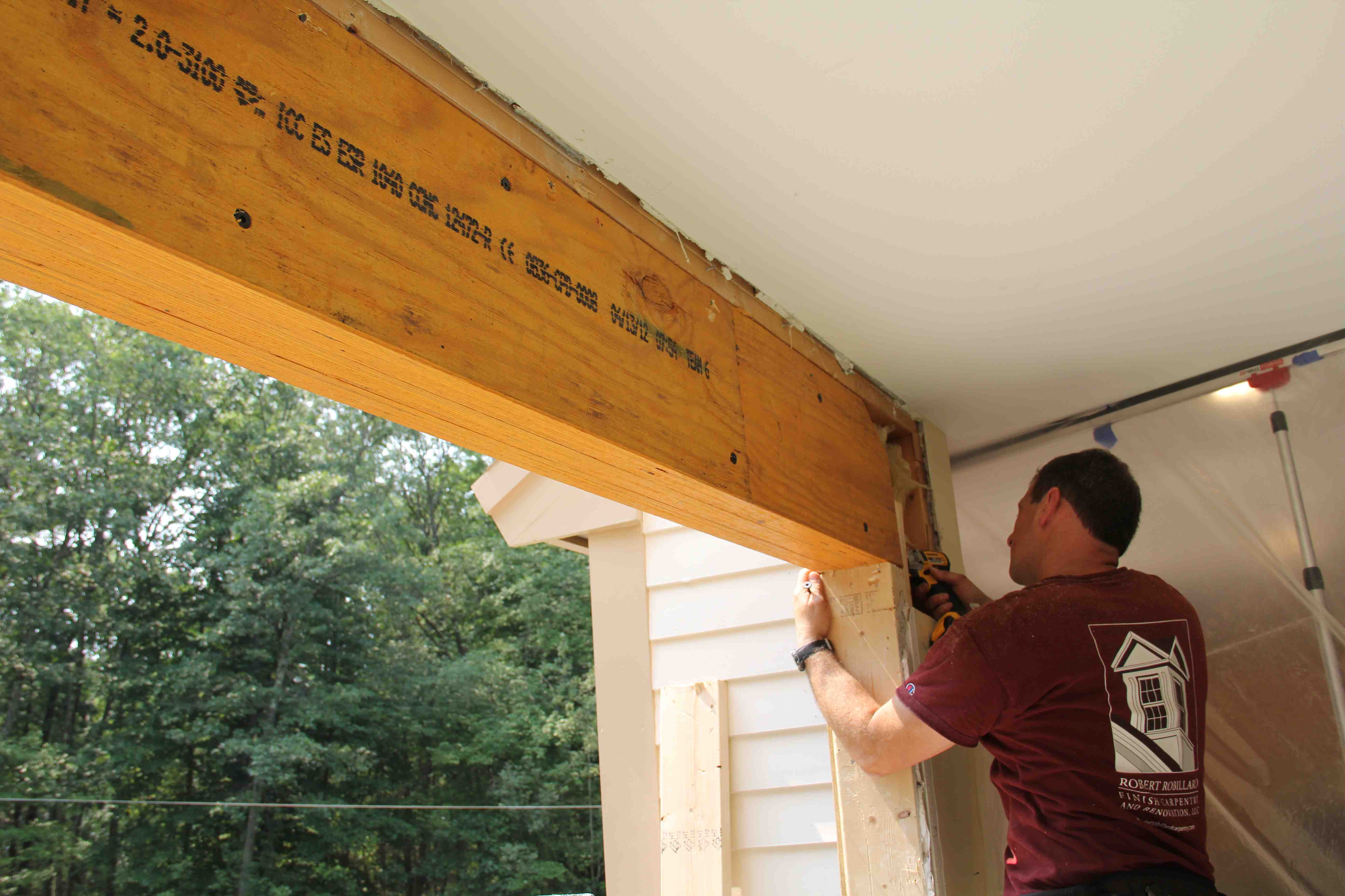
In our case we noticed loading once the two vertical posts were removed. Weight loading the temporary studs will occur once you remove the bearing wall, or beam. Place a stud under each ceiling joist and use two or three 3- inch #10 deck screws. Ensure a snug fit, by cutting your studs about 1⁄8 to 1⁄4 inch long and tap place. TIP: Before building your temporary walls talk to the steel fabricator and see what they need for clearance for their equipment Temporary Support WallsĪttach temporary wall studs to top and bottom plates 2 to 3 feet back from the wall or beam. In some cases one lift will suffice and that lift will be centered under the beam. 48” of clearance was needed directly below, and on each end, of the beam. The beam weighed more than one lift could handle, so two lifts were used. In our case we built our walls 4 feet back due to the kitchen island and the need for a 4-foot corridor to allow the Sumner Roust-A-Bout Lift to roll in. This is needed to access the ceiling framing, relocate wires, pipes, and to install your temporary support walls. Strip the ceiling back 2 -3 feet back from the wall to be removed or beam, and install your temporary wall. Then remove or relocate wires, pipes or duct-work that will be in the way of the beam. Prior to removing a bearing wall, remove the wall or ceiling board to expose the framing.

Bevel the edges of your 2×8 to fit tight against the web. TIP: When installing the solid wood the area where the top and bottom flanges meet the vertical I-beam web is slightly rounded.

This solid wood allows for attachment of the joists via joist hangers. This is called “packing the beam,” the three 2×8 boards were needed to extend past the top and bottom steel flange. Solid wood was installed on each side of the beam. TIP: Threaded rod is more affordable, and is easily sourced. Carriage bolts or threaded rod can be used to secure the wood to the beam. The holes allow solid lumber to be bolted to the beam. We supplied the steel company with the floor joist layout, so they could drill the 1/2” holes in between the floor joists. Note – with steel beams the engineer, may specify 4×6 PSL posts secured with metal connectors, or steel posts welded to steel plates. The PSL posts transfer the weight to other posts or the foundation below So we turned to a local steel company that supplies, preps and installs the beam. We supplied the steel company with the length of beam which was the entire beam length minus ¼” and specified that we wanted the beam to fit inside a 2×10 joist bay. The steel company uses a local structural engineer who specified a W8x58 steel beam with 4×6 PSL posts. Once recessed the LVL beam would project 8 to 10 inches below the ceiling. Our problem was that the span required an LVL that was MUCH deeper than the floor joists. We first started off working with our lumberyard who specified an LVL beam.


 0 kommentar(er)
